
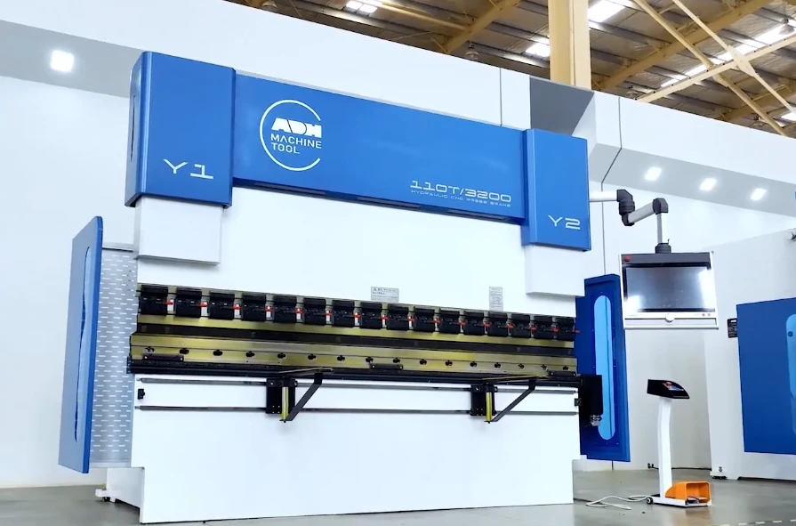
While laser cutting and turret punching transform flat sheet metal into flat two-dimensional blanks, CNC Press Bending turns those flat blanks into three-dimensional structural enclosures, brackets, and channels. By driving a hardened upper punch down into a V-shaped lower die, a press brake applies concentrated bending moments along straight lines.
Despite its mechanical simplicity, precision sheet bending requires careful management of material elastic recovery (springback), directional grain orientation, and tonnage limits to achieve repeatable bend angles within tight tolerances ($pm 0.5^circ$).
1. Mechanics of Sheet Bending: Air Bending, Bottoming, and Coining
Sheet metal bending relies on three distinct process methods, each offering different trade-offs between required machine tonnage, angle flexibility, and springback control:
-
THREE BENDING METHOD SCHEMATICS
-
1. AIR BENDING 2. BOTTOMING 3. COINING
-
(3-Point Contact) (Full Die Seat) (Extreme Penetration)
-
Punch Punch Punch
-
| | |
-
v v v
-
/ / /
-
/ / /
-
+—–+ +—–+ +—–+
-
/ | / / / /
-
/ | / / / /
-
+—–+—–+ +–+—–+–+ +–+—–+–+
-
V-Die V-Die V-Die
-
Touch at 3 points; Sheet seats fully; Punch stamp deforms
-
angle set by depth. requires 3-5x tonnage. neutral axis (5-10x ton).
-
+———————————–+
-
| BENDING METHOD COMPARISON |
-
+—————–+—————–+
-
|
-
+—————————+—————————+
-
| | |
-
+—–+—–+ +—–+—–+ +—–+—–+
-
| Air Bending | | Bottoming | | Coining |
-
+———–+ +———–+ +———–+
-
• 3-point material contact • Material seats in die • Extreme tonnage deforms axis
-
• Angle set by punch depth • Fixed angle (88°/90°) • Eliminates all springback
-
• Lowest required tonnage • Moderate springback • Severe tool wear & limits
-
• Universal tool setups • High tonnage required • Highest precision & stress
1. Air Bending
In air bending, the punch forces the sheet into the V-die opening without pressing it against the bottom of the tool. The sheet makes contact at only three points: the tip of the upper punch and the two upper edges of the lower V-die.
Because the bend angle is determined entirely by the penetration depth ($Y$-axis stroke) of the ram, a single set of $85^circ$ tools can produce any bend angle from $180^circ$ down to $85^circ$ simply by adjusting the stroke depth. Air bending requires the lowest tonnage, making it the most common approach in modern flexible CNC sheet metal fabrication.
2. Bottoming (Bottom Pressing)
In bottoming, the punch forces the sheet down until it contacts the side walls and bottom of the lower V-die. The final bend angle is determined by the tool geometry (typically $88^circ$ or $90^circ$ punches and dies). Bottoming requires 3 to 5 times more tonnage than air bending, but it reduces springback variation caused by subtle batch-to-batch material thickness differences.
3. Coining
Coining subjects the material to extreme compressive stress (requiring 5 to 10 times the tonnage of air bending). The punch tip penetrates past the material’s yield point across its entire cross-section, permanently setting the neutral axis and eliminating springback. Due to high tool wear and machine stress, coining is largely restricted to thin, high-precision military or aerospace components.
2. Elastic Recovery and Springback Compensation Mechanics
When a press brake releases its bending load, the elastic strain stored within the metal relaxes, causing the bent angle to open up slightly. This phenomenon is known as springback.
-
SPRINGBACK ELASTIC RELAXATION DYNAMICS
-
Under Load (Punch Down) Unloaded (Punch Retracted)
-
Punch Punch
-
| ^
-
v |
-
/ /
-
/ /
-
/ /
-
+—–+ +——-+
-
| θ | | θ + Δθ|
-
+—–+ +——-+
Key Variables Influencing Springback
-
Material Yield Strength ($sigma_y$): Higher-strength alloys (e.g., structural stainless steel or high-tensile strength steel) exhibit significantly greater elastic recovery, requiring larger springback compensation.
-
Internal Bend Radius ($R$) to Thickness ($T$) Ratio: As the $R/T$ ratio increases, a larger portion of the material cross-section remains within the elastic deformation zone during bending, leading to higher springback ($Deltatheta$).
Real-Time CNC Compensation Systems
Modern CNC press brakes use real-time angle measuring systems to achieve precise bends on the first hit:
-
Laser Angle Measurement Systems: Optical sensors project laser lines against both legs of the sheet during the stroke. The CNC controller calculates the real-time angle, compares it to target geometry, over-bends the part slightly to compensate for predicted elastic recovery, and confirms the final resting angle upon ram retraction.
-
REAL-TIME LASER ANGLE MEASUREMENT
-
Upper Ram / Punch Tool
-
|
-
Laser Emitter —> | <— Laser Emitter
-
/
-
/
-
+——/———–+
-
| Sheet Material |
-
+——————-+
-
Camera Camera
-
Sensor Sensor
-
Reads live angle & adjusts ram depth on-the-fly
3. Bend Allowance, K-Factor, and Flat Pattern Calculation
To accurately size flat laser-cut blanks before bending, engineers calculate the exact amount of material consumed along the bend zone. When metal is bent, the outer surface stretches in tension while the inner surface compresses.
-
BEND CROSS-SECTION NEUTRAL AXIS
-
Inner Surface (Compression)
-
+—————————+
-
| . . . . . . . . . . . . . |
-
| – – Neutral Axis (t) – – | <— No stress / length change
-
| . . . . . . . . . . . . . |
-
+—————————+
-
Outer Surface (Tension)
Between these regions lies the Neutral Axis—a plane through the sheet thickness that undergoes zero longitudinal length change during forming.
The K-Factor Formula
The position of the neutral axis relative to total material thickness ($T$) is defined by the dimensionless $K$-Factor:
$$K = frac{t}{T}$$
Where $t$ is the distance from the inside bend surface to the neutral axis, and $T$ is the total material thickness.
-
For small radii ($R < T$), $K approx 0.30 text{ to } 0.38$.
-
For standard air bending ($R approx T$), $K approx 0.40 text{ to } 0.45$.
-
For large radii ($R gg T$), $K approx 0.50$ (neutral axis approaches the center of the sheet).
Calculating Bend Allowance ($BA$)
Using the $K$-Factor, the total arc length along the neutral axis—known as the Bend Allowance ($BA$)—is calculated using:
$$BA = frac{pi}{180} times theta times left( R + K times T right)$$
Where:
-
$theta = text{Included Bend Angle (Degrees)}$
-
$R = text{Inside Bend Radius (mm)}$
-
$T = text{Material Thickness (mm)}$
-
$K = text{K-Factor}$
4. Multi-Axis Backgauge Motion and Crowning Compensation
To produce complex parts with multiple bent flanges, a CNC press brake uses automated multi-axis backgauges and bed deflection compensation systems.
-
MULTI-AXIS BACKGAUGE ARCHITECTURE
-
Punch Tool / Ram Axis (Y1, Y2)
-
|
-
v
-
+——————————————-+
-
| Workpiece Sheet |
-
+——————————————-+
-
| |
-
+———–+ +———–+
-
| Backgauge | | Backgauge |
-
| Finger 1 | | Finger 2 |
-
+———–+ +———–+
-
[ X, R, Z1 ] [ X, R, Z2 ]
Multi-Axis CNC Backgauge System
High-precision backgauge systems move rapidly between bends along multiple independent axes:
-
$X_1 / X_2$ Axes: Controls forward/backward depth positioning for flange length accuracy.
-
$R_1 / R_2$ Axes: Adjusts vertical finger height to accommodate pre-bent flanges.
-
$Z_1 / Z_2$ Axes: Drives the left/right lateral position of fingers across the width of the machine bed.
-
BED DEFLECTION AND CROWNING
-
Without Crowning (Bending Force Deflects Bed):
-
===================== Upper Ram =====================
-
/
-
+— Sheet Material —+ <– Over-bent at ends,
-
/ under-bent in middle
-
===================== Machine Bed ===================
-
With Dynamic Mechanical Crowning:
-
===================== Upper Ram =====================
-
========================
-
+— Sheet Material —+ <– Uniform angle across
-
======================== entire length
-
================ Curved Wedge Bed ===================
Hydraulic and Mechanical Crowning
Under heavy bending loads, both the upper ram and lower bed deflect outward at the center. Without correction, this deflection causes parts to over-bend near the ends and under-bend at the center.
To compensate, modern CNC press brakes use crowning systems (either hydraulic cylinders embedded in the lower bed or motor-driven mechanical wedges) that apply an upward counter-curve across the center of the bed, ensuring uniform bend angles along the entire length of the part.
Summary
Precision CNC press brake bending bridges the gap between 2D flat metal blanks and functional 3D components. By understanding the mechanical differences between air bending, bottoming, and coining, compensating for material springback with real-time laser measurement, using accurate $K$-factor formulas for flat pattern development, and employing multi-axis backgauges with dynamic crowning, fabricators produce accurate, repeatable sheet metal geometries across varying production run sizes.
Stainless steel pipes kampala uganda
